Step 9 of 8: Evaluation
Near Point Vision
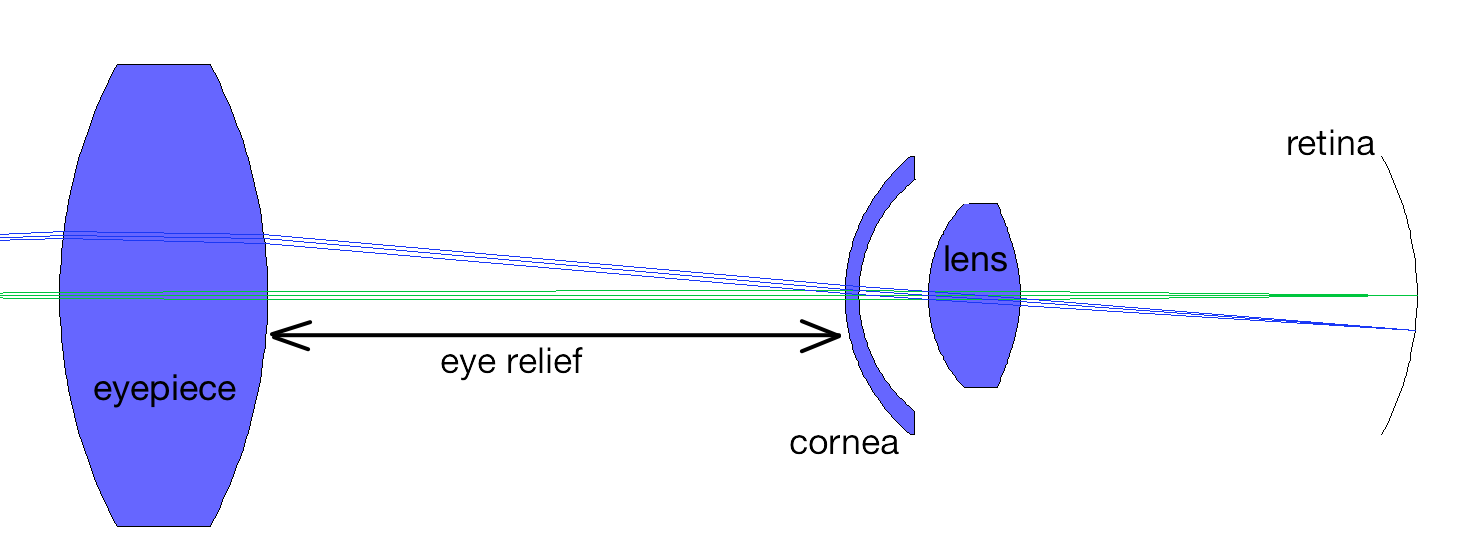
Our telescope is afocal and therefore no image is formed. This is odd because when you look through a telescope, there is an image. What's up? Well, the cornea and lens of your eye will image distant objects onto your retina. The closest distance that an object can be from the eye and still be focused is called the near point and is accepted to be 250mm. (Younger eyes can focus closer and older ones need more distance.)
So, let's place the image surface (IMS) in the OSLO simulation at the location of the virtual image formed by the telescope. This means that the image surface should be located 250mm to the left of the last surface of the eyepiece. So we set the distance from the last surface to the image surface to -250mm.
Eye Relief
Unfortunately, we need to worry about the distance from the last optical surface to the cornea of the eye. Obviously, we will not be touching our eye to the eyepiece lens! The distance between an optical instrument and the eye is called the eye relief. For a telescope it is about 25mm. This means that we should use -225mm instead of -250mm.
Let's start with the DCX telescope. We would like the light arriving from infinity to be imaged onto the screen 225mm to the left of the last surface. (Our paraxial design placed the image infinitely far away. To evaluate the telescope, it is handy to just set the image surface at -225 after the last surface. To see what we're doing we also force the image surface (IMS) to be drawn (Special Button -> Surface Control -> General -> Surface Appearance -> Drawn).
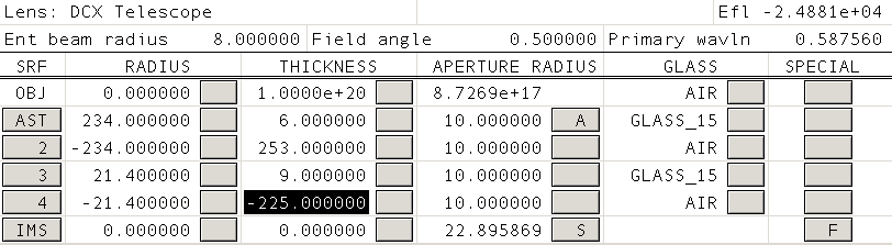
To see what we're doing we also force the image surface (IMS) to be drawn. That is what the "F" hints at in the last line. You achieve this by clicking the button in the "Special" column in the last row. Then select Surface Control -> General -> Surface Appearance -> Drawn.
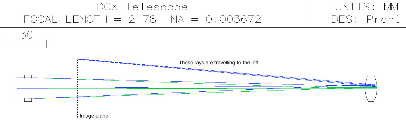
So which parameter in our telescope design can we change? Since we're stuck using surplus lenses, the only parameter that we can change is the distance between the lenses. We will change this number to focus the light onto the image surface. If you haven't done this before then you should start by manually changing the thickness of the second surface to see how tightly you can focus the axial beam and the beam at 2 degrees.
Slider wheel
Typing numbers into the spreadsheet gets old fast. Moreover, it becomes hard to tell exactly when the best distance has been reached. We can visually optimize the focus in another way by using the "slider-wheel" feature of OSLO. This option creates a linear slider control that changes on variable. (The "wheel" part is to remind you that you can use the scroll-wheel on your mouse to move the thumb too.)
Under the optimize menu, select "Slider-Wheel Design" and fill in the elements to match the screen capture below. This will create a control that allows you to dynamically change the thickness of the second surface. By selecting "Ray-intercept" and "All points" the error in focus will be shown for on-axis light, light entering at 0.35 degrees, and light entering at 0.5 degrees.
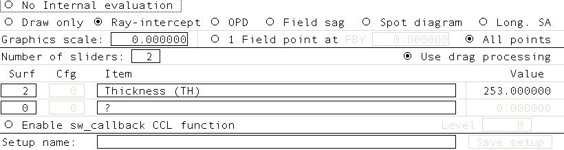
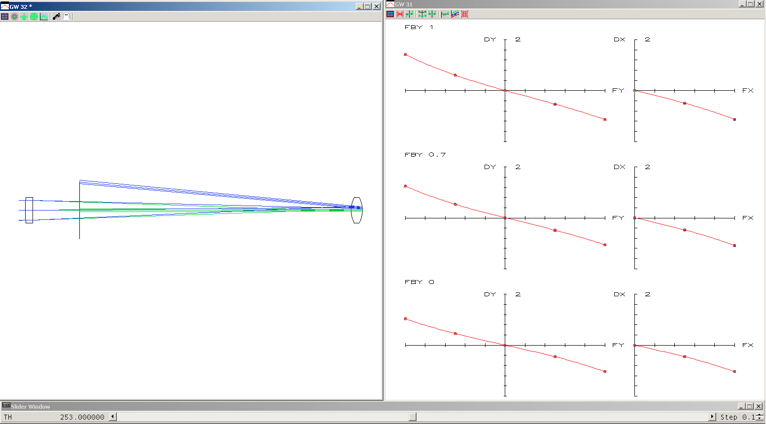
Click the checkmark and resize the windows so that you have something like the image shown below. Your goal is to move the slider so that lines in the right hand window are located on the horizontal. (The number "2" in the graphs indicates that the focusing error is nearly 2mm for the 0.5 degree beam.)
How do we know that 2mm is large, well the entire image of the moon only has a radius of 22.9mm (the aperture radius for the image surface is automatically calculated). The diameter is then about 46mm and therefore 2mm is a significant part of this image!
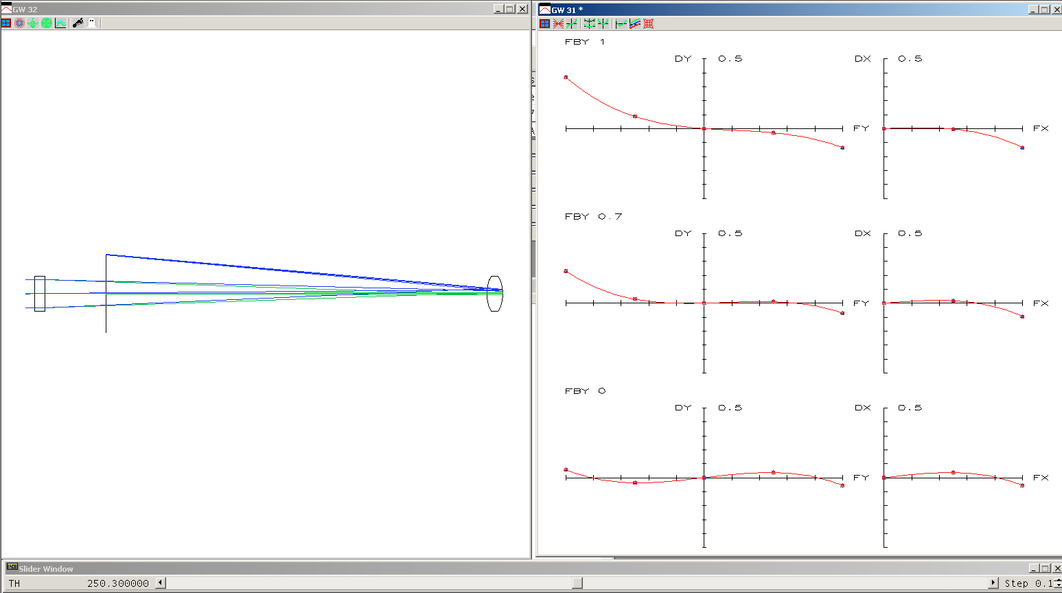
By adjusting the slider you can end up with a smaller misfocus that looks like
When you repeat the process for the PCX telescope, you'll find that that trade-offs are more severe — as you improve focus for the parallel rays, those for the 2 degree rays become much worse. Ultimately, this is what I settled on
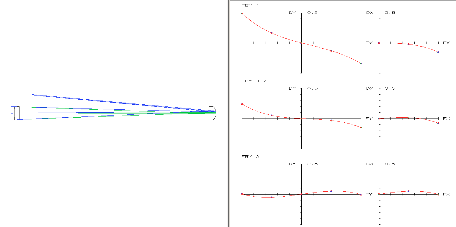
And therefore the DCX telescope works a bit better than the PCX telescope.
But wait, does it? We have completely omitted looking at chromatic aberrations because we have directly specified that the index of refraction is 1.5 for all wavelengths. What happens when the glass in the lenses is BK-7?