Overview
This is the second part of a tutorial that covers OSLO basics; specifically, how to enter lens data into OSLO. In particular, it explains how to set the size of the object and select rays to be traced.
The FAQ may give you a hint or two that will make the OSLO experience a bit less horrible.
The first part of this tutorial should have gotten you to the point of entering most of the lens data into the
Surface Dataspreadsheet.This tutorial is one from a list of other tutorials that are available.
New ideas
Setting the index of refaction
Using
Pickupto automatically update cellsUsing
Setupto set the object heightUsing
Autofocus - paraxialto automatically focusForce drawing of surfaces
Set the height of an object
Selecting the rays to be traced
Modifying the entrance beam diameter
The Problem
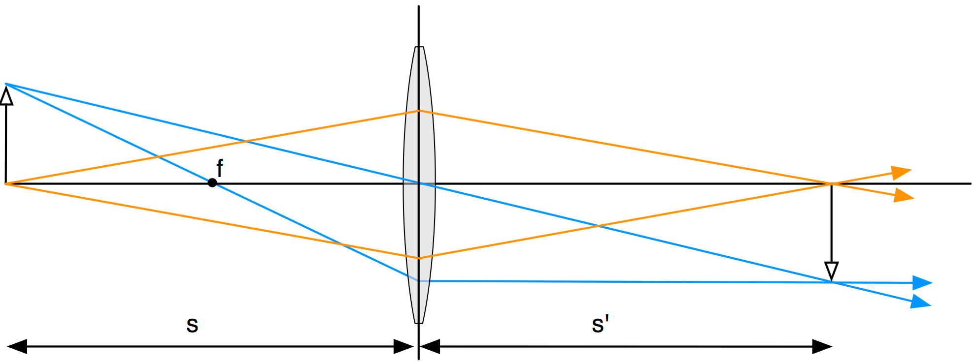
The problem is to ray trace light from an object through a biconvex lens to the image plane.
- The focal length of the lens should be 50mm
- The index of refraction of the lens is 1.5
- The object is 100mm from the lens.
- The object height is 15
- The lens diameter is 38mm
- The lens thickness is 8mm
Setting the index of refraction
Instead of using a real glass with chromatic dispersion, we want this lens to have an index of refraction equal to 1.5
Specifically this means that the first surface AST should have an index of refraction of 1.5. To do this, click on the button in the glass column of the AST line. Select Direct... from the pop-up menu and you'll see
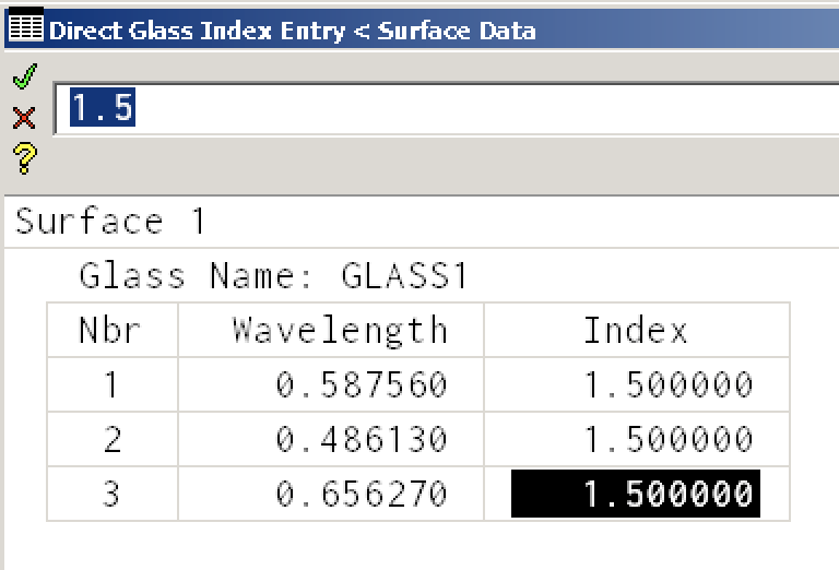
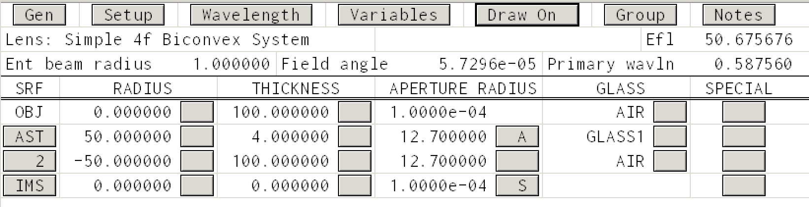
where I have already changed the refractive index at each wavelength to 1.5. Click the green check box in the upper left hand corner of the dialog box and your Surface Data spreadsheet should look like
The three wavelength are traditional optical design wavelengths and correspond to easily obtained Fraunhofer emission lines for green, blue, and red light.
| Helium | d-line | 587.56nm | Green |
| Hydrogen | F-line | 486.13nm | Blue |
| Hydrogen | C-line | 656.27nm | Red |
Drawing the Optical System
Click on the Draw Off button
You should now see something like
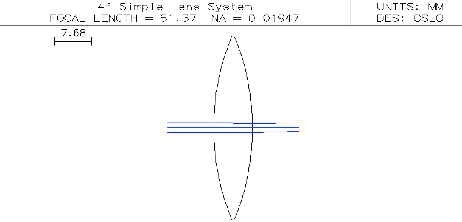
So far, so good. However,
- the focal length of the lens is not 50mm
- the object is not visible
- the image is not apparent
- the rays are smushed together
Let's fix each of these in turn.
Fixing the focal length
The easiest way to get the focal length to be 50mm is to change the curvature of the lenses. Because this lens is equi-convex, we'll modify one of the radii of curvatures to automatically be entered as the negative of the first surface radius of curvature.
To do this, click on the button in the RADIUS column of the row numbered 2. Select Minus Curvature Pickup and answer 1 when asked to Enter the pickup source surface and then click OK for the next two dialog boxes.
Now when you change the RADIUS of first surface (the AST surface), the RADIUS of the second surface will automatically get updated. Try this.
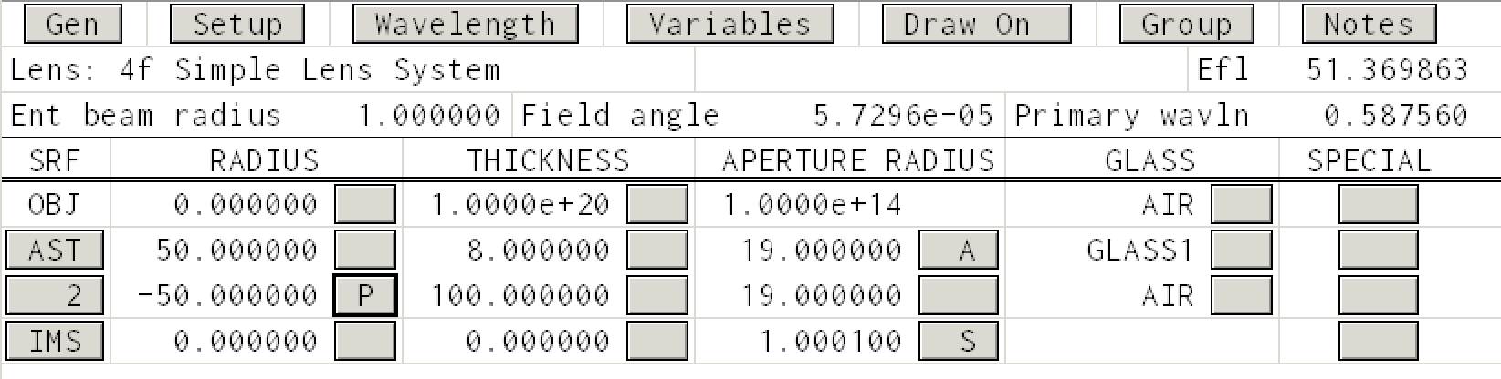
Now repeatedly change the radius until you obtain an effective focal length to be 50mm as shown below.
Now, in a sense, you have designed your first lens.
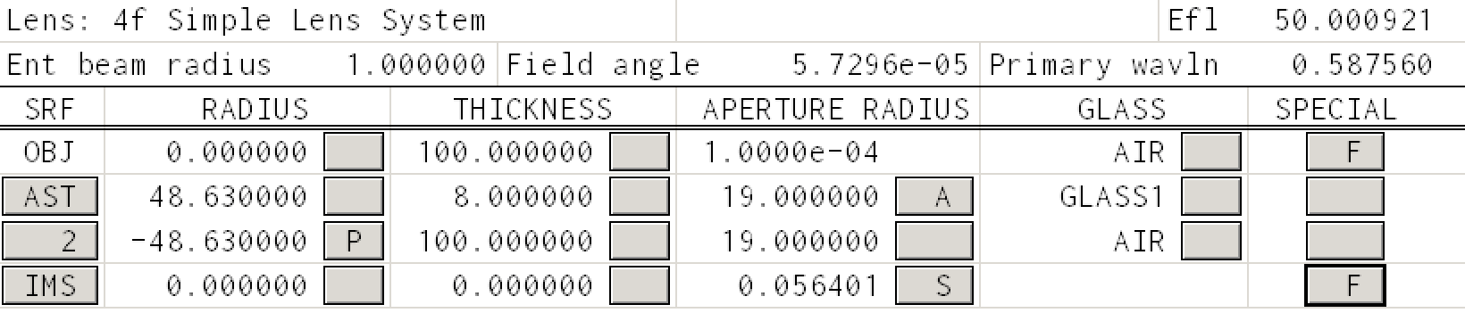
Telling OSLO to Show the Object and Image
To force OSLO to show the OBJ and IMS surface, one uses the button in the SPECIAL column.
In the OBJ row click the button and navigate Surface Control (F) -> General to get the following dialog box
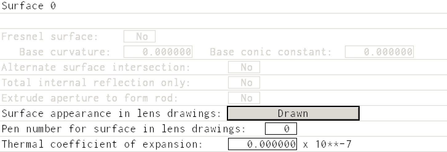
Change the appearance from Automatic to Drawn
Do the same for the IMS surface. The drawing should look like
and the Surface Data spreadsheet should look like
Increasing the object size
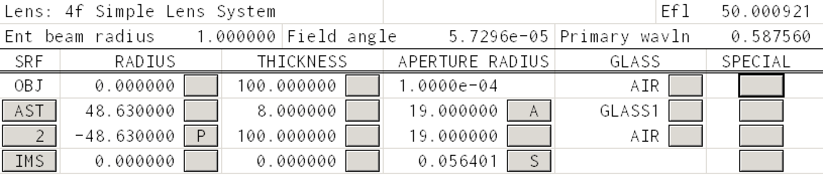
You cannot change the object height (APERTURE RADIUS) by just clicking and entering the object height. Instead, you must click the Setup button in the Surface Data window. Here there is a place to specify the object height.
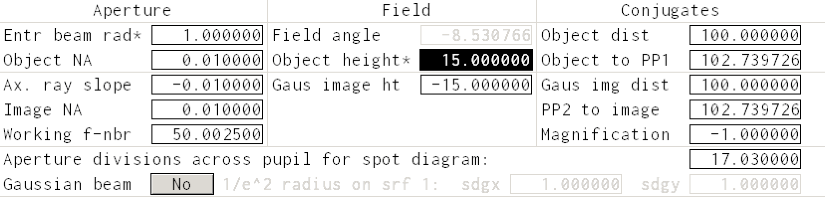
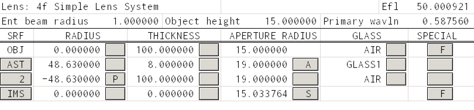
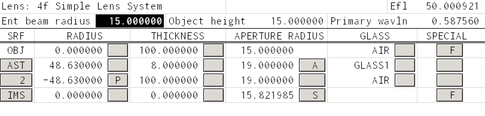
After entering the object height as 15mm, the Surface Data spreadsheet should be
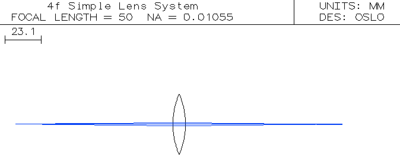
the system should look like
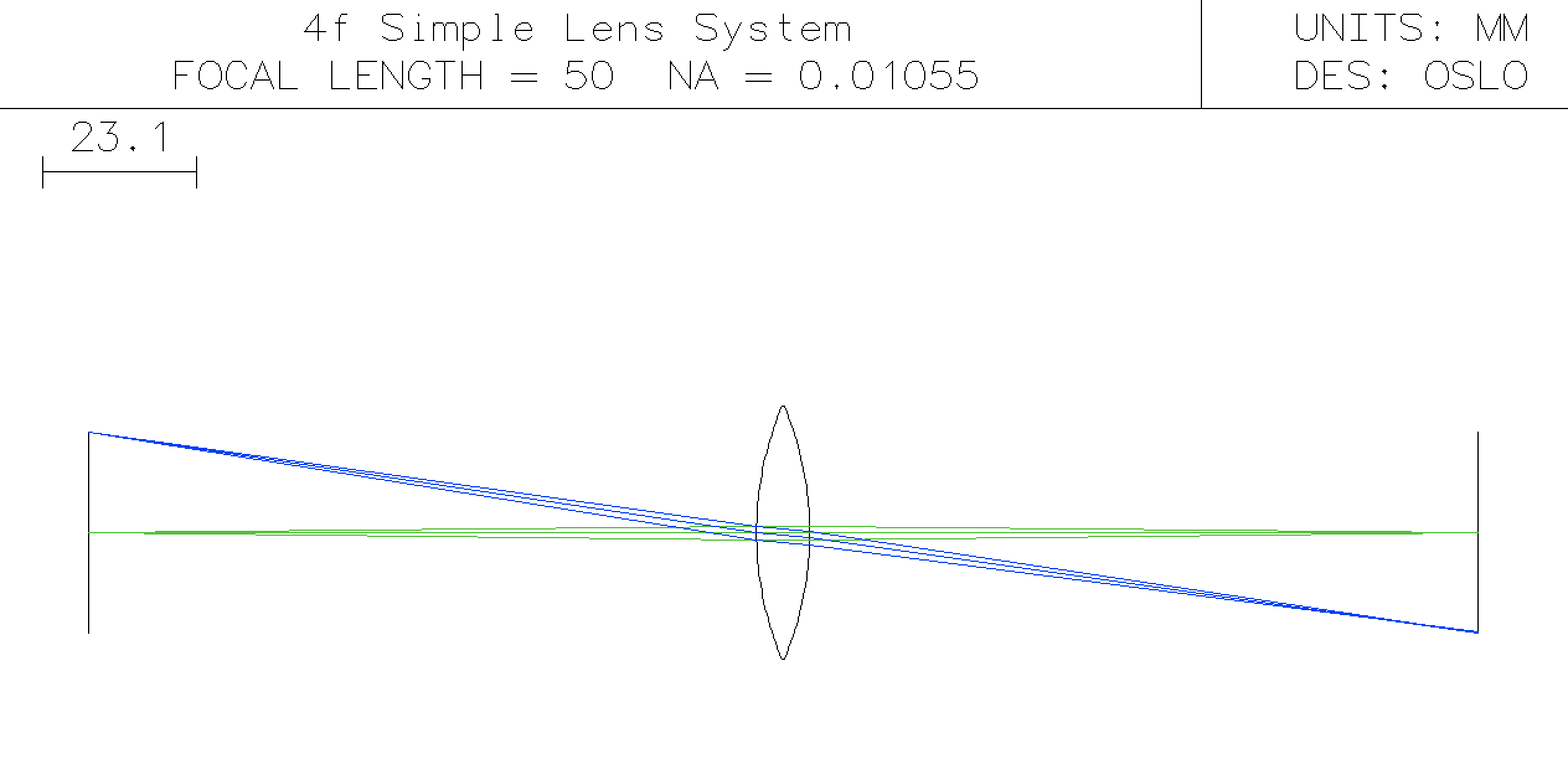
Now this is close to the desired system layout. The object is imaged nicely at the image plane that is 100 mm from the back surface of the lens.
Using more of the lens
In the image above, only the most central rays are shown. How do we trace rays through the top and bottom of the lens?
This is a 38mm lens with a 19mm aperture. What if we want to see rays at 15mm from the center?
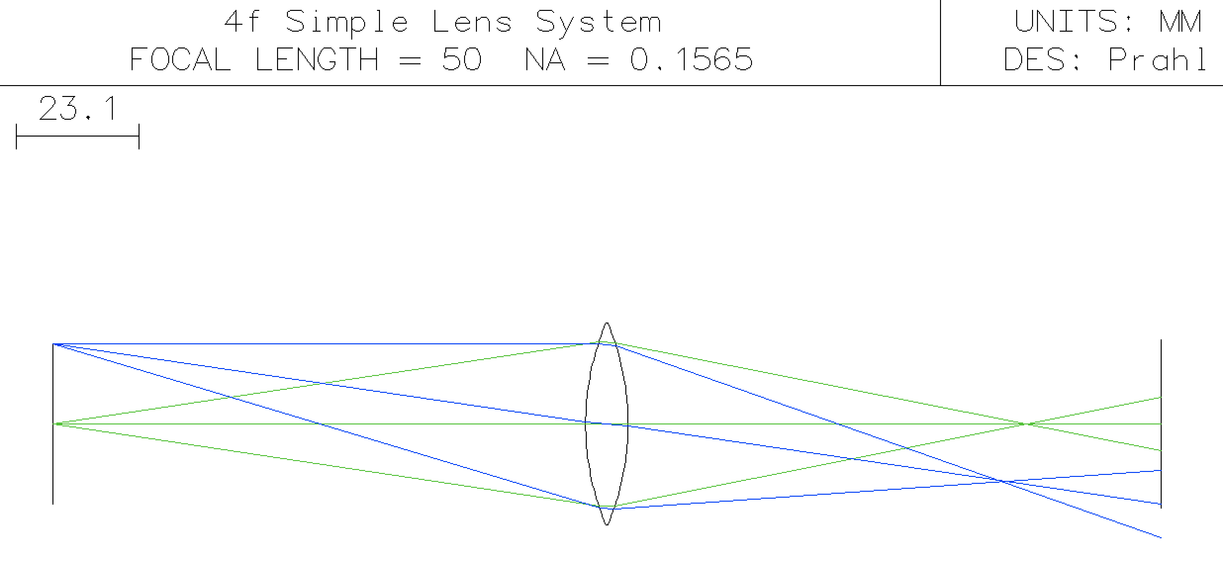
The trick here is to change the Ent beam radius (entering beam radius) to 15mm. (This is the radius for a ray in the aperture plane --- in this example the first surface.)
Now the Surface Data spreadsheet should be
the system should look like
Changing the rays that are drawn
What if we just want to trace a bunch of rays from the top of the object? In this case the Surface Data spreadsheet should be
Go to the Lens menu and select Lens Drawing Conditions ... to get the following dialog box.
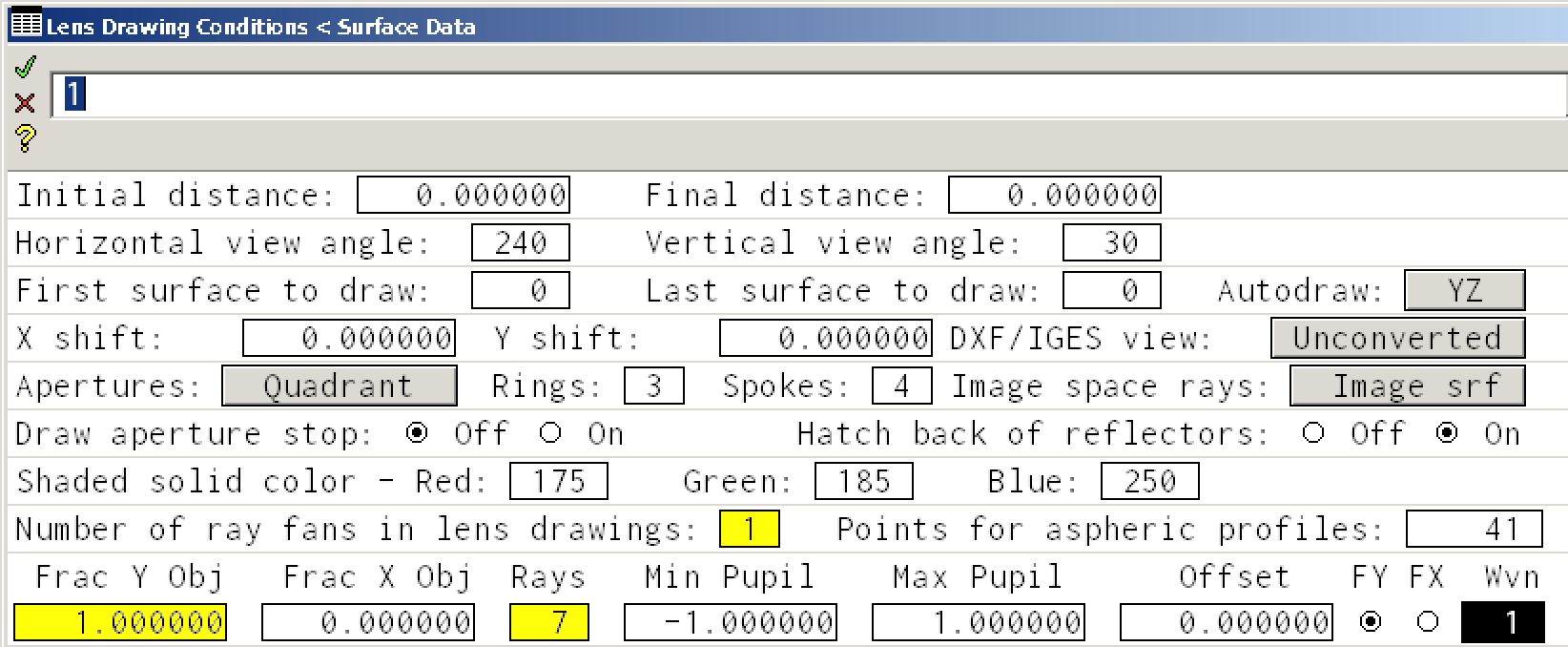
By changing boxes in yellow, you can obtain the following drawing that draws seven rays from the top of the object
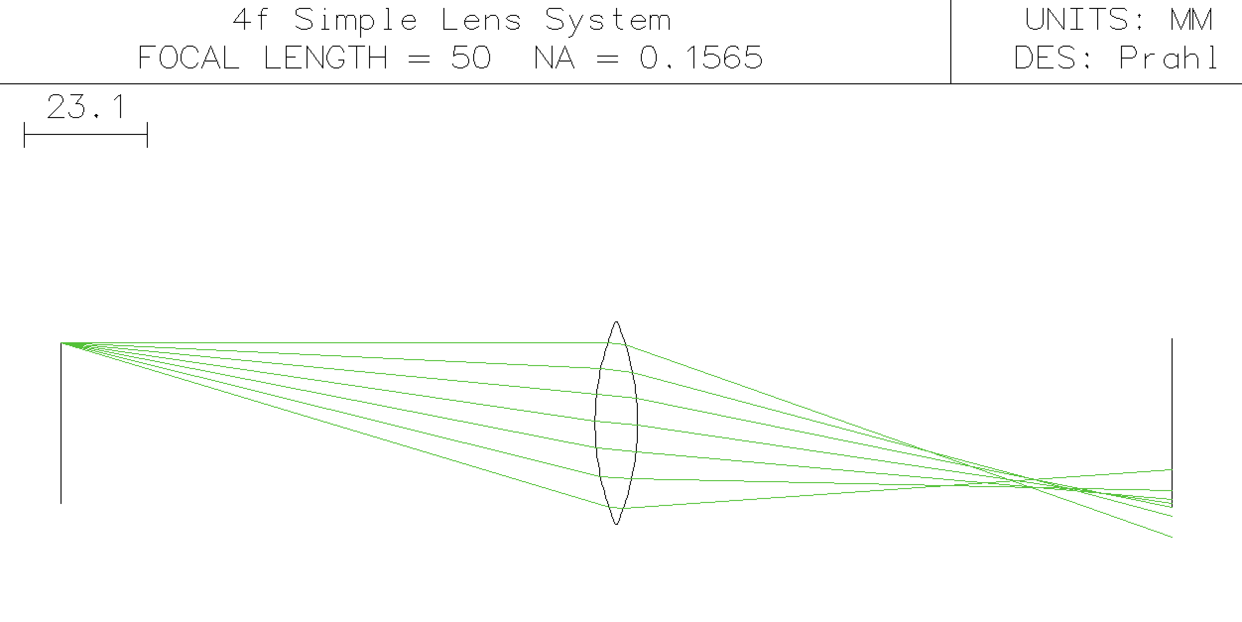
These rays do not cross at the image plane like the paraxial ones did. Spherical aberrations are really big. This is why small F# lenses (ratio of focal length to aperture diameter) that focus well are expensive.
Next steps
The next tutorial will cover the basics of mirrors.
The next tutorial will introduce OSLO optimizations.
This document is also available as a Jupyter notebook as simple2.ipynb.
© 2019 Scott Prahl