Overview
This is the first part of a tutorial that covers the fundamental ideas of most ray tracing programs and OSLO in particular. Ast the end you should be ready to enter most of the lens data into the Surface Data spreadsheet.
The FAQ may give you a hint or two that will make the OSLO experience a bit less horrible.
The second part, explains how to set the size of the object and select rays to be traced.
This tutorial is one from a list of other tutorials that are available.
New ideas
Surfaces are numbered based on their vertices
Weird numbering for surfaces (e.g.,
OBJ,AST, orIMS)RADIUSmeans radius of curvatureTHICKNESSmeans distance to next surfaceAPERTURE RADIUSis one-half the diameter of the optical elementGLASSmeans index of refraction of the material following the surface
The Problem
The problem is to ray trace light from an object through a biconvex lens to the image plane.
- The focal length of the lens should be 50mm
- The object is 100mm from the lens.
- The object height is 15
- The lens diameter is 38mm
- The lens thickness is 8mm
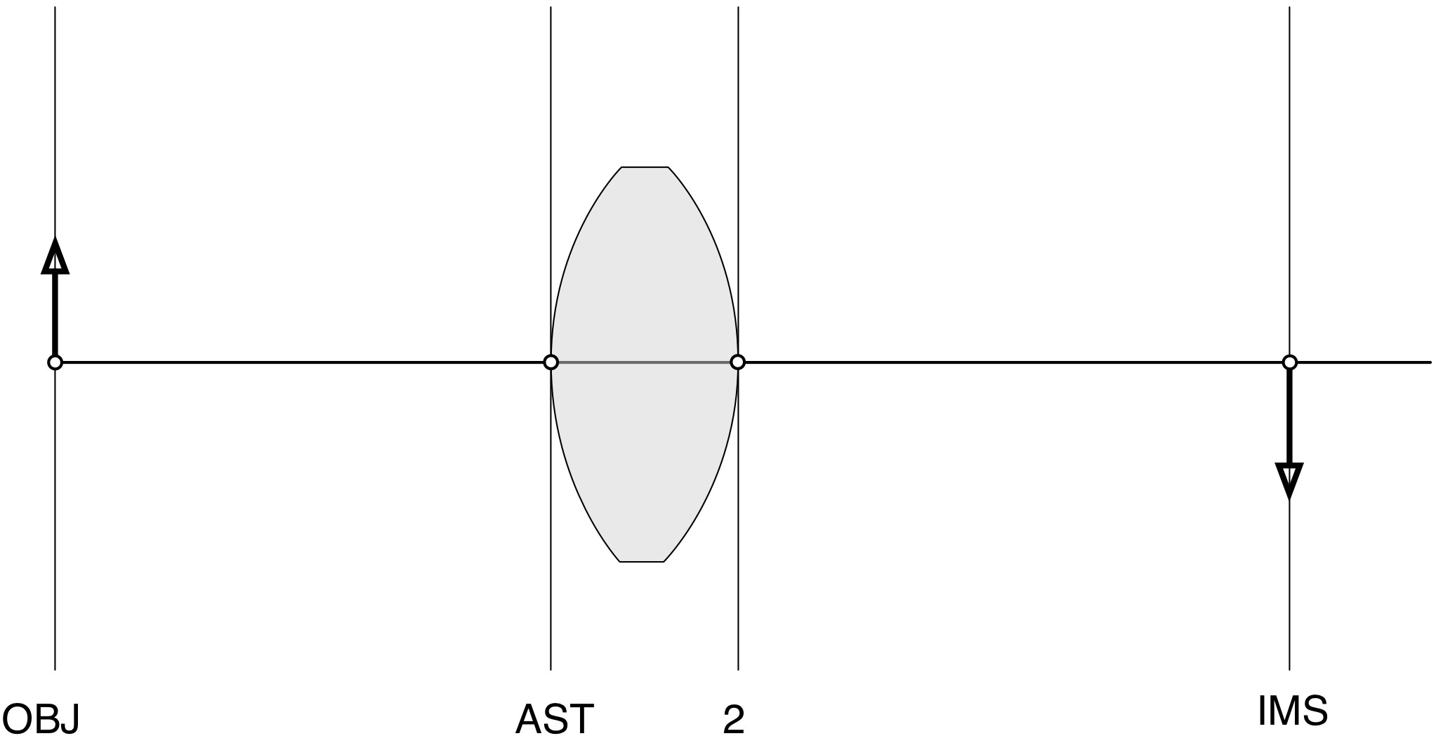
The conventional paraxial ray trace through this 4f system would look like
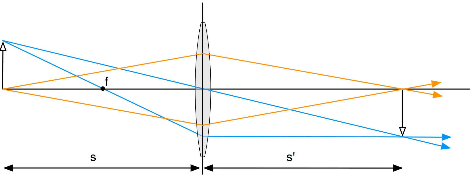
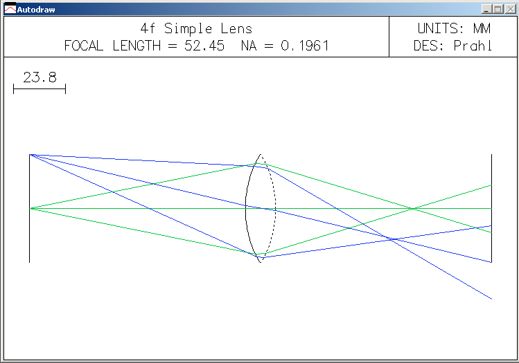
The intersection of the two blue rays (or two orange rays) determines the image plane. The OSLO result below shows that the paraxial approximation is pretty poor for this case!
The Basics
OSLO requires a complete description of the optical system as a series of numbers; these are organized into the Surface Data table. Each row of the table describes a different surface and each column refers to a different property of that surface. Entering the correct numbers is made more difficult because OSLO's column headers have precise meanings that will inevitably differ from yours.
The basic inclination of most students who are asked to solve a problem with OSLO is to immediately start entering numbers into the Surface Data window and then becoming frustrated because nothing really works. I am sure you're not one of those students.
Finding and entering each number is simple, but they all must be done perfectly because OSLO does not award any partial credit.
The first few times that you use OSLO, I suggest that you labor through ALL of the steps below. Once you become more familiar with OSLO the entire sequence can be reduced to an initial sketch with notes. The steps are
- Sketch the Optical System
- Find the Vertex for each surface
- Find the Curvature of each surface
- Find the Distance to next surface
- Find the Height of each surface
- Find the Material to next surface
- Tabulate the result
Sketch the Optical System
Don't use a computer for this step. Use a piece of paper.
Just do it. I know that you're clever and can keep everything in your head at once (especially for this trivial system).
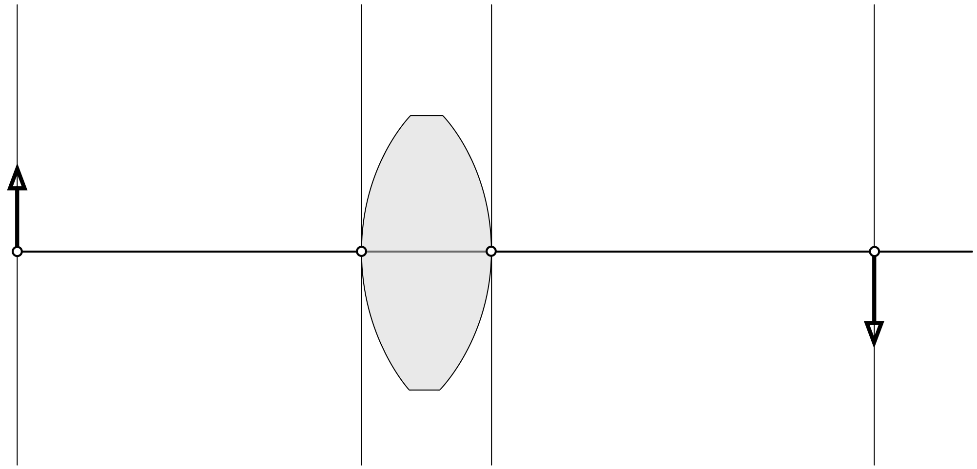
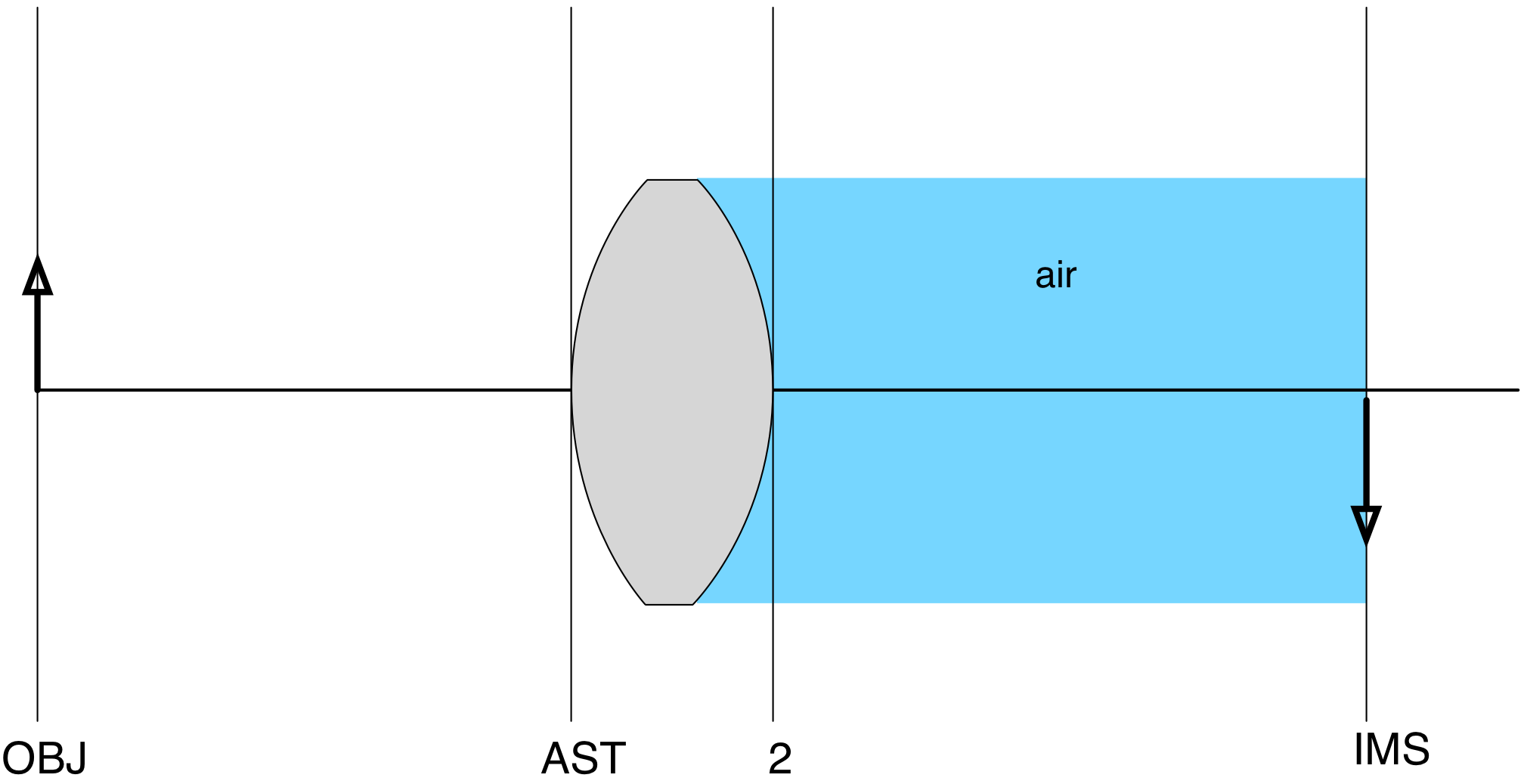
Your sketch should have an optical axis and all the optical elements. In this case that means an object plane, the lens, and the image plane.

If you don't have a sketch, then you won't be able to play along at home.
Find the Vertex for each surface
Identify the vertex of each surface by finding where it crosses the optical axis. The vertical lines are just for finding distances and identifying surfaces.
Now label the surfaces. Start at the left with the object surface "OBJ". The next surface to the right is "1", followed surprisingly by surface "2". The last surface is the image surface "IMS".
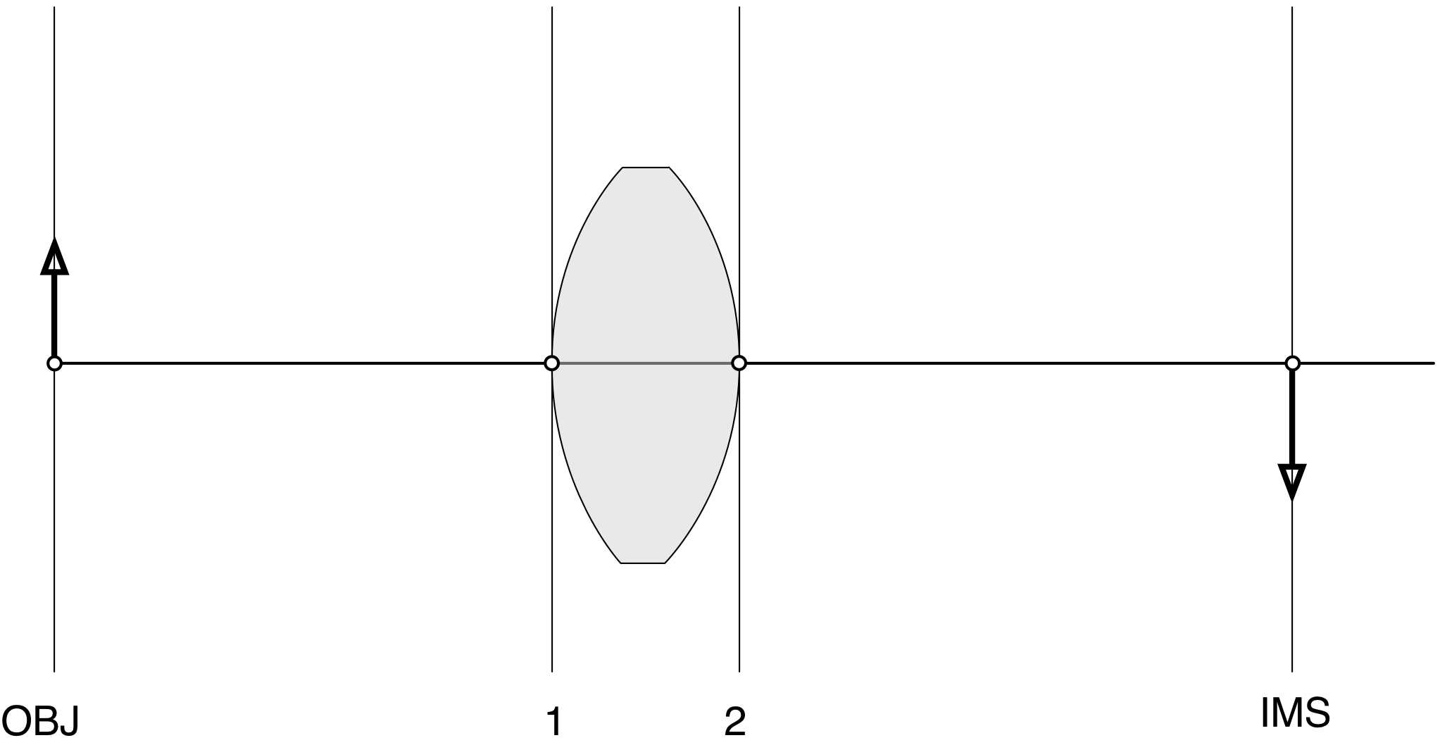
Unfortunately, OSLO's programmers did not like this numbering scheme. Instead, they observed that in any optical system, one surface will always be the aperture stop "AST". Therefore one surface must be labelled "AST". Whether or not this is a good and interesting thing is not something that you are allowed to have an opinion about. For our optical system, it makes no difference, so we will just label the first surface "AST" instead of "1".
So far, you're killing it. Am I right?
Find the Curvature of each surface
We need to know the curvature of the first (AST) surface. The lensmaker's equation for a thin lens is
$$
{1\over f} = (n-1)\left({1\over R_1} - {1\over R_2}\right)
$$
where, of course, $R_1$ is the radius of curvature of the first surface,
$R_2$ is for the second surface, and $f$ is the focal length of the lens.
Now, since the lens is equi-convex, the radius of curvature of one side is the negative
of the radius of the other side so $R_1=R=-R_2$ so
$$
{1\over f} = (n-1)\left({1\over R} - {1\over (-R)}\right)
$$
Now we can solve for the radius of curvature
$$
R = {f\over 2(n-1)}
$$
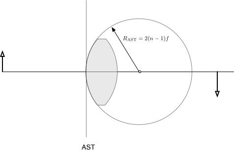
- OSLO defines positive radii as those with a center to the right of the vertex.
- OSLO defines negative radii as those with a center to the left of the vertex.
In this case, the radius of curvature of the first surface is positive because the sphere's center is to the right of the vertex.
The second surface has a negative radius of curvature because the sphere's center is to the left of the vertex

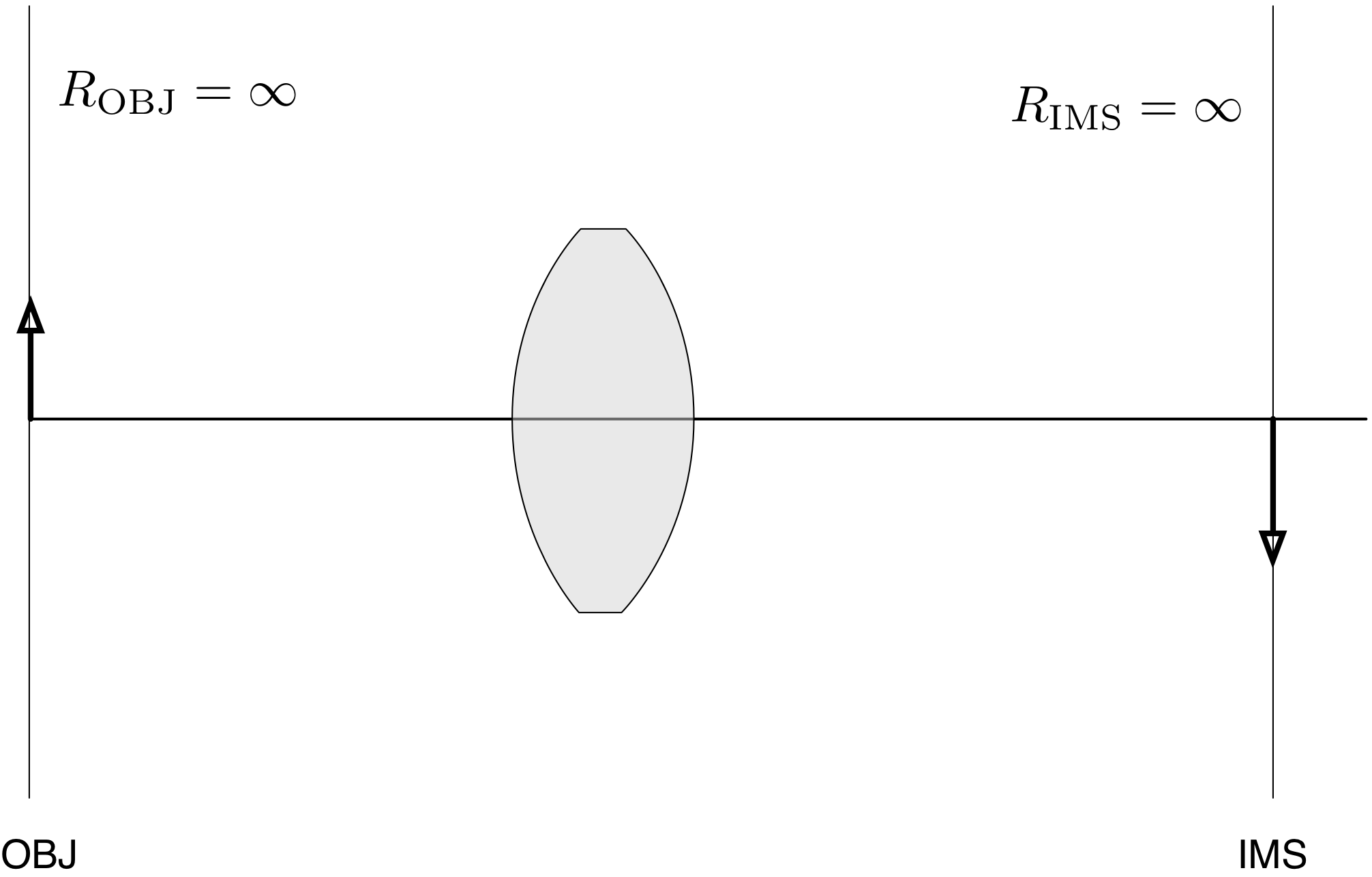
The object and image surfaces also have radii of curvatures. Since they are flat, this corresponds to a circle that is infinitely big and so, of course, are infinite.
OSLO allows one to write
0to represent infinity for radii
Now, collect all the curvatures in one place
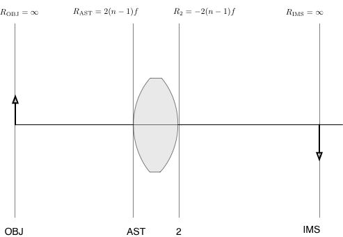
Collect these curvatures into a table describing your optical system.
| Surface | Curvature | Distance | Height | Material |
|---|---|---|---|---|
| OBJ | 0 | |||
| AST | $R_{AST}$ | |||
| 2 | $R_2$ | |||
| IMS | 0 |
Find the distance to the next surface
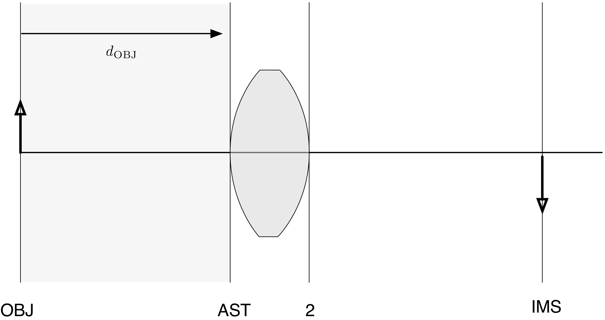
This is easy. The tricky part is that what is measured is the distance to the next surface. Thus, the object (OBJ) distance is
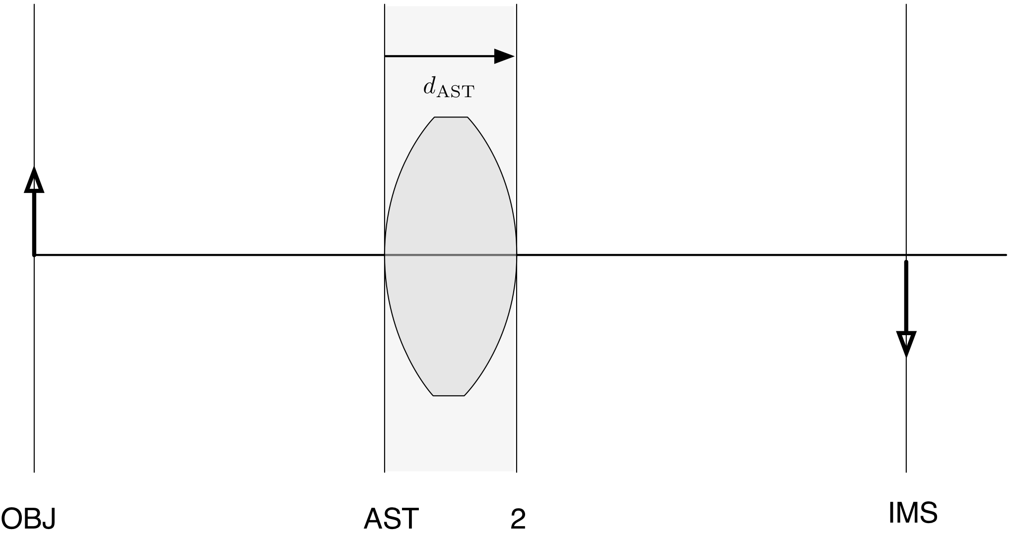
 The distance of the first surface (the AST surface) is the thickness of the lens from vertex to vertex
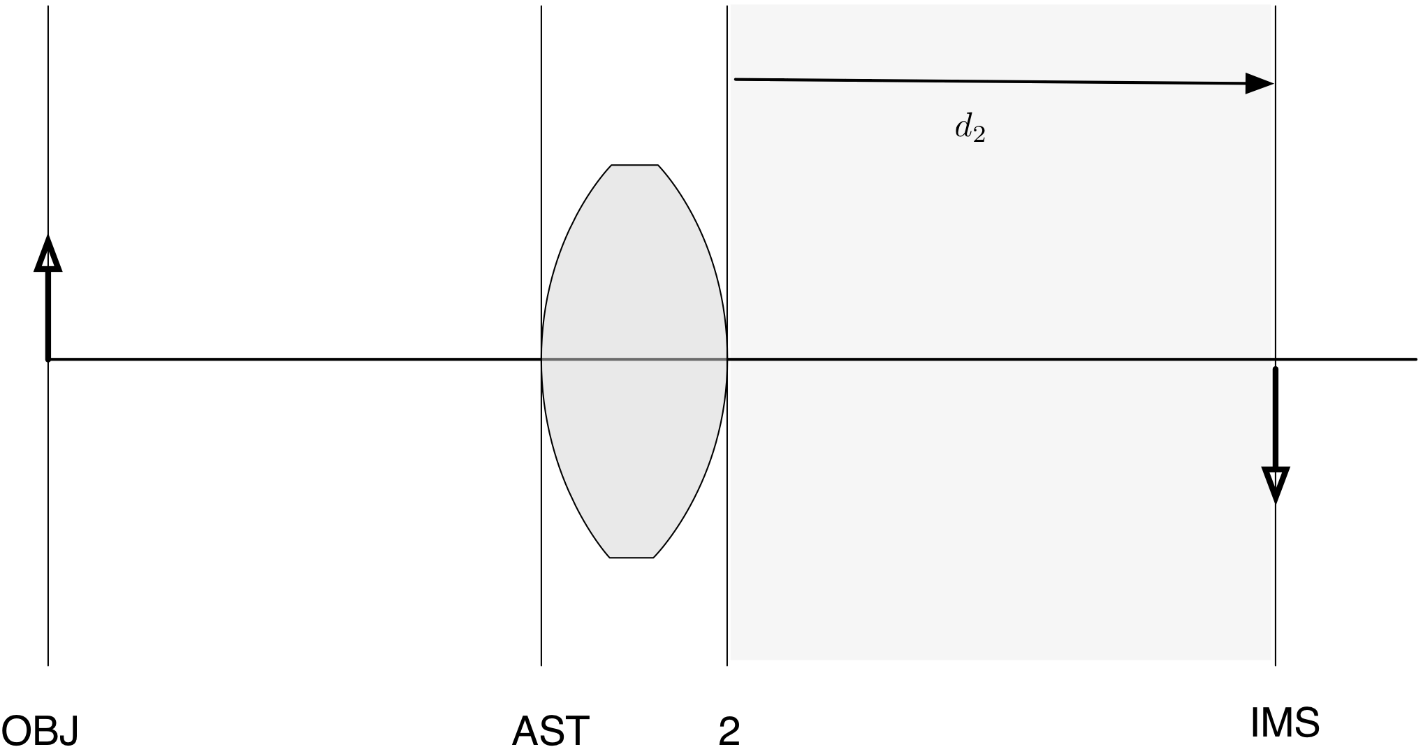
 The distance for the second surface is the length to the image surface. You
don't need to set this distance because OSLO can calculate it for you.
The distance for the second surface is the length to the image surface. You
don't need to set this distance because OSLO can calculate it for you.
So, now add these distances to your table describing the single lens system.
| Surface | Curvature | Distance | Height | Material |
|---|---|---|---|---|
| OBJ | 0 | $D_{OBJ}$ | ||
| AST | $R_{AST}$ | $D_{AST}$ | ||
| 2 | $R_2$ | $D_2$ | ||
| IMS | 0 | (calc) |
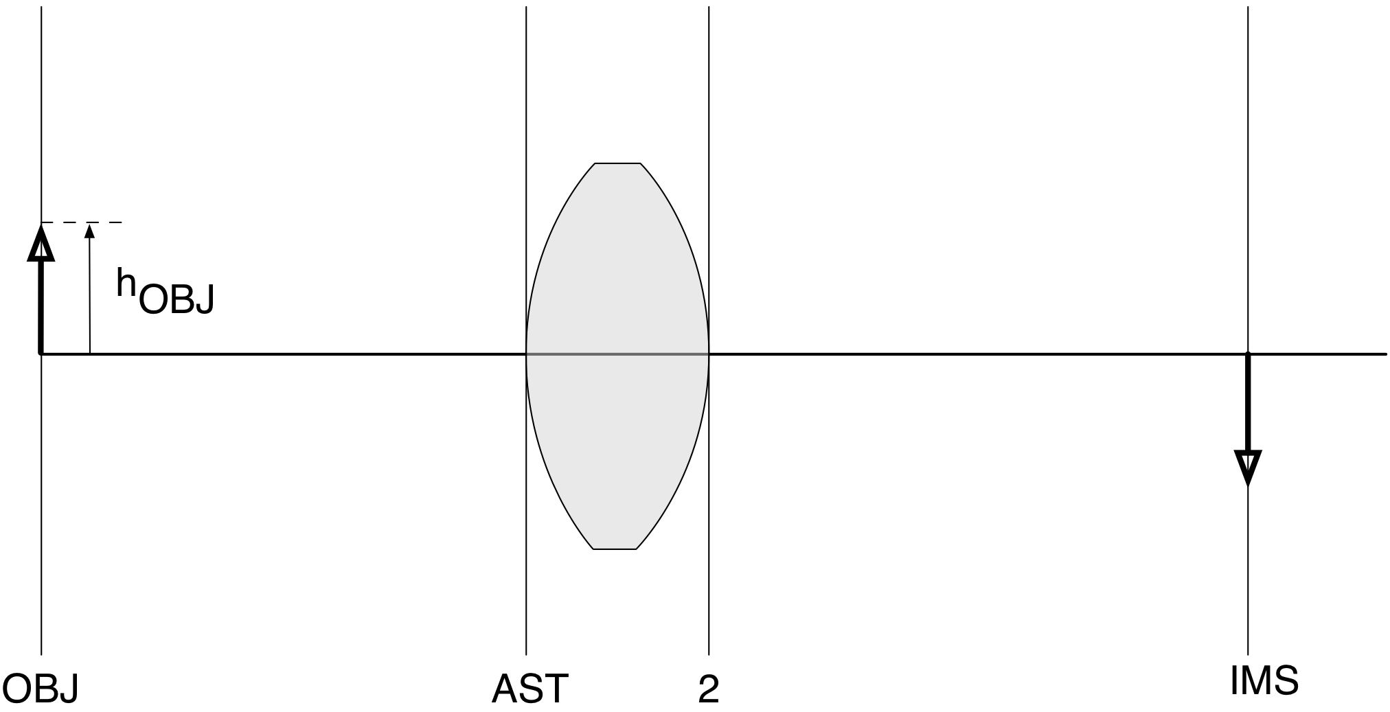
Find the height of each surface (from the optical axis)
This is really easy. The only confusing part is that you'll be determining the height of the object from the optical axis (or its radius). The object (OBJ) height is
 The height of the first surface (the AST surface) is
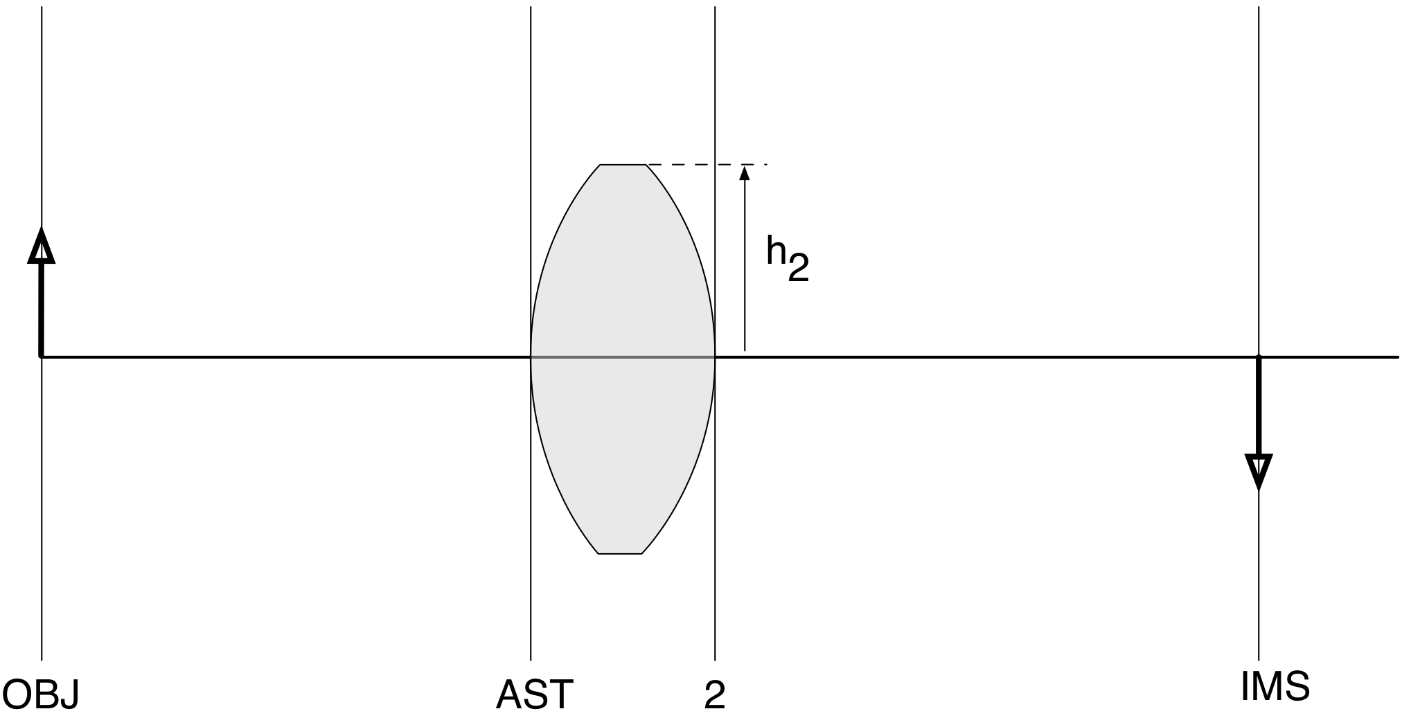
 The height of the second surface should be the height of the previous surface
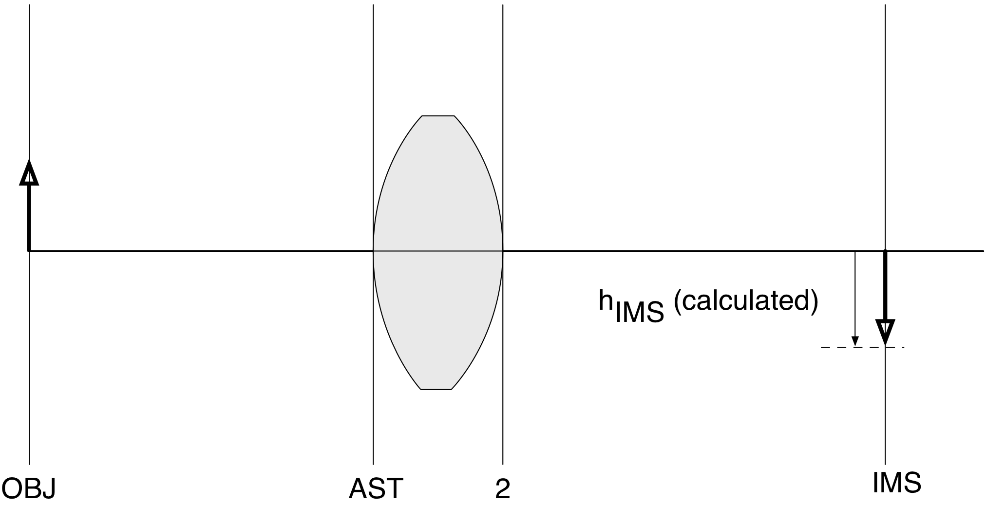
 The height of the image surface can be left blank. OSLO will calculate it for you.
So, once again, add these heights into the table describing your optical system.
| Surface | Curvature | Distance | Height | Material |
|---|---|---|---|---|
| OBJ | 0 | $D_{OBJ}$ | $h_{OBJ}$ | |
| AST | $R_{AST}$ | $D_{AST}$ | $h_{AST}$ | |
| 2 | $R_2$ | $D_2$ | $h_2$ | |
| IMS | 0 | (calc) | (calc) |
Find the material to next surface
This is also easy.
The tricky part is that the material for each surface comes after the surface. Thus, in our case, the material for the OBJ surface is just air.
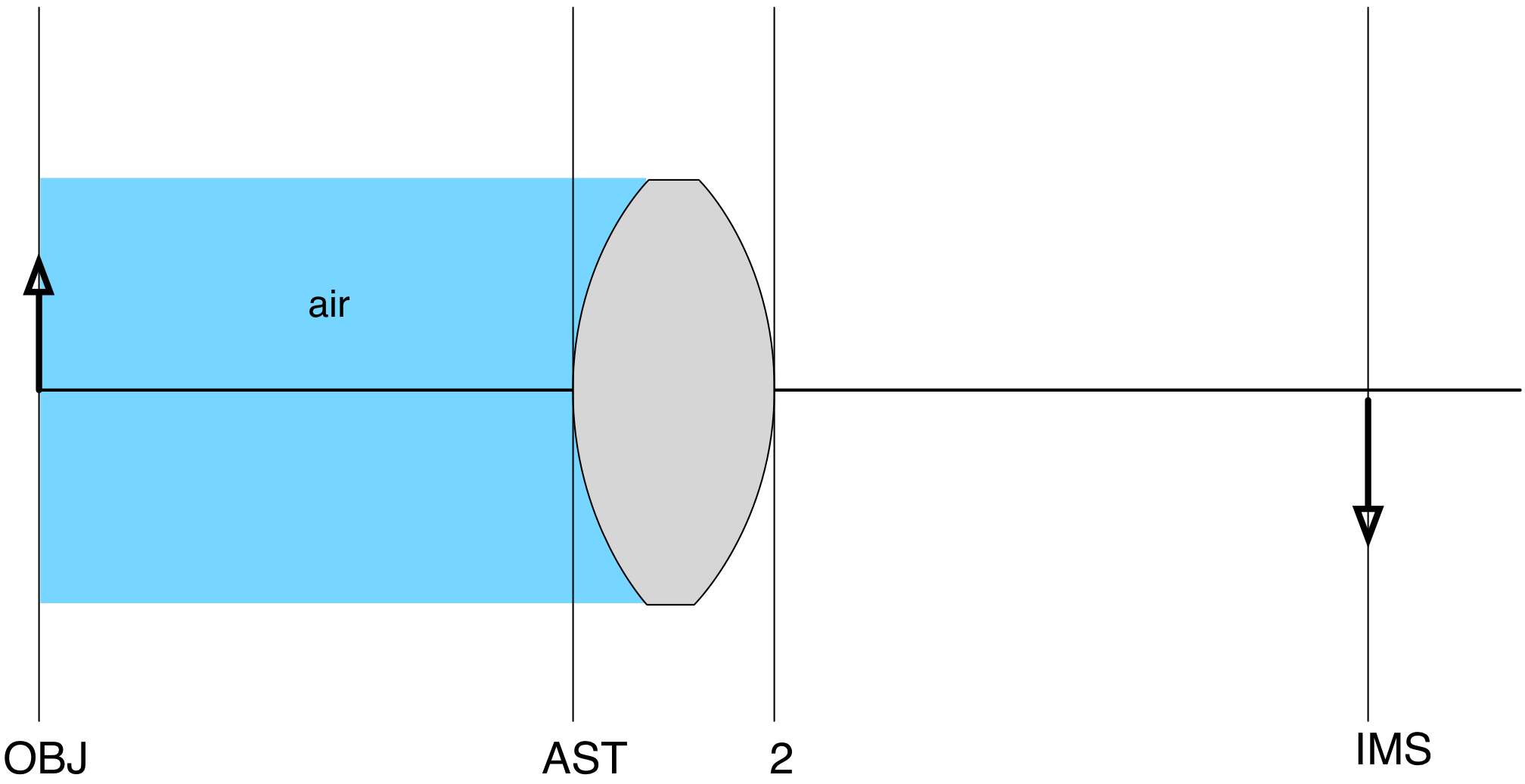
The material for the next surface (the AST surface) is the glass that the lens is made from
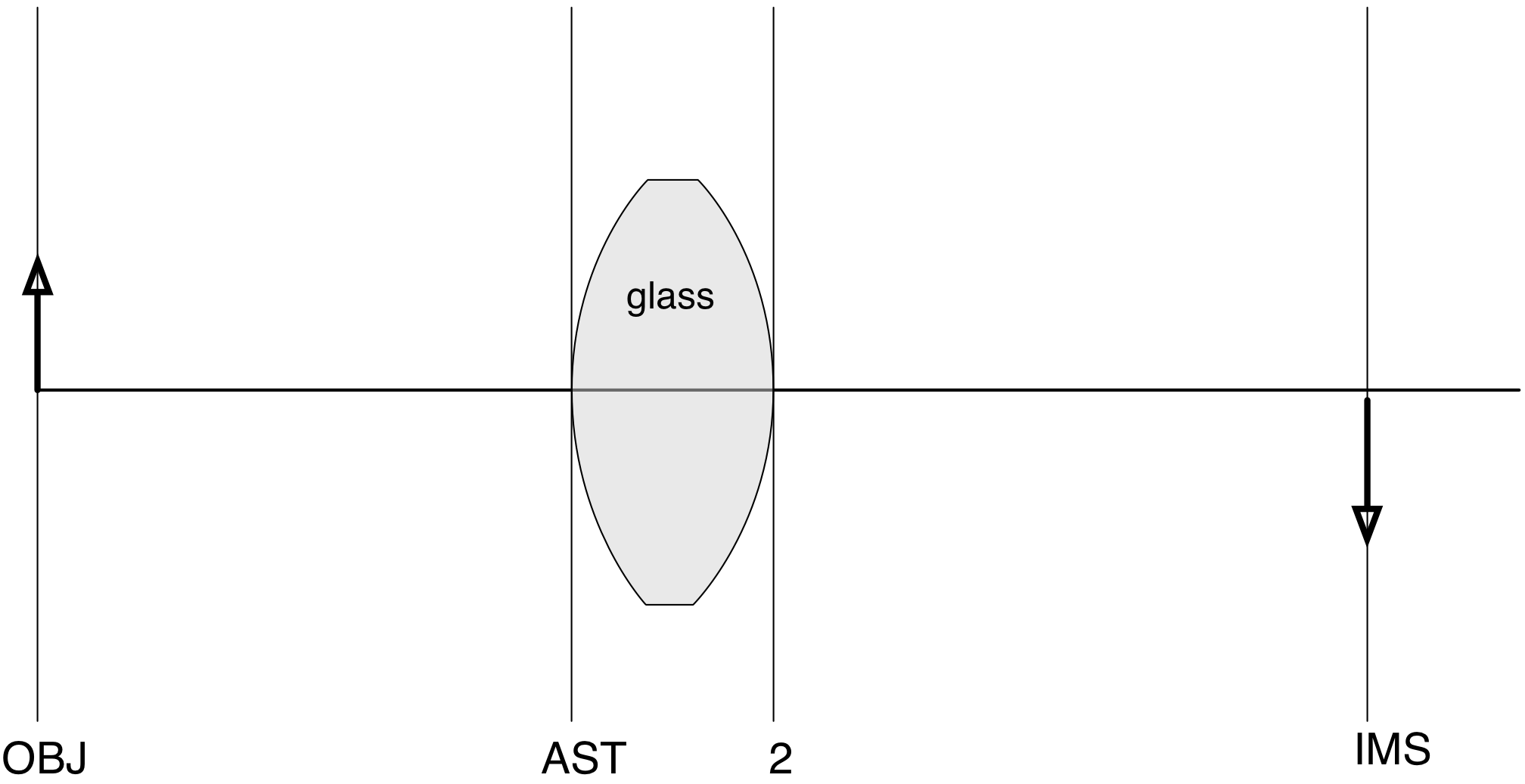
The material for the next surface is air again!
Once again, you don't have to worry about the last surface and can leave it as air. So, the table describing your optical system is
| Surface | Curvature | Distance | Height | Material |
|---|---|---|---|---|
| OBJ | 0 | $D_{OBJ}$ | $h_{OBJ}$ | air |
| AST | $R_{AST}$ | $D_{AST}$ | $h_{AST}$ | glass |
| 2 | $R_2$ | $D_2$ | $h_2$ | air |
| IMS | 0 | (calc) | (calc) | air |
Finally, start using the OSLO names
OSLO uses different names for each column. OSLO's names kind of make sense, but they're more ambiguous than the ones that we used. For example, "height" becomes "APERTURE RADIUS" as you can see below.
| SRF | RADIUS | THICKNESS | APERTURE RADIUS | GLASS |
|---|---|---|---|---|
| OBJ | 0 | $D_{OBJ}$ | $h_{OBJ}$ | air |
| AST | $R_{AST}$ | $D_{AST}$ | $h_{AST}$ | glass |
| 2 | $R_2$ | $D_2$ | $h_2$ | air |
| IMS | 0 | (calc) | (calc) | air |
So how do you do this? Open a new lens file in OSLO. The Surface Data window will look like this. The headings are the same as the ones above.
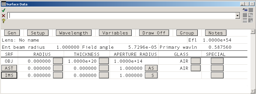
Notice that we need one more surface (row). There are many ways to add rows, but the simplest is to select the image surface row (by clicking on the IMS button) and typing Ctrl+I.
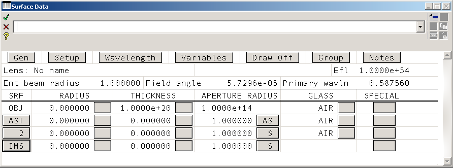
And now it is just a matter of entering the data that you have collected in the table above into your new Surface Data Window.
Next steps
The next tutorial will give step by step instructions for finishing this simple lens design.
This document is also available as a Jupyter notebook as simple.ipynb.
© 2019 Scott Prahl