Overview
This is an OSLO tutorial about ray tracing with mirrors. It is really basic, but it does assume some familiarity with OSLO. If you are just starting out with OSLO then you probably want to start with Single-lens Ray-Trace Tutorial
This tutorial is one from a list of other tutorials that are available.
The FAQ might also be of help.
New ideas:
Mirrors are created by setting the
GLASStoREFLorREFL_HATCHAfter the mirror, light travels to the left so
THICKNESSis a negative numberThe signs for the radius of curvature are the same independent of the direction of travel
If the light is reflected back through the same optical elements, these surfaces must be repeated
# Execute this cell first
%matplotlib inline
import numpy as np
import matplotlib.pyplot as plt

def efl_thick_mirror(n, R1, R2, d):
    """
    Calculates effective focal length of a lens that has the R2 surface mirror coated.

    Args:
    n  - index of refraction of the lens
    R1 - radius of curvature of first surface of lens [mm]
    R2 - radius of curvature of second (mirror coated) surface [mm]
    d  - thickness of the lens [mm]

    Returns:
    EFL - effective focal length (mm)
    """
    return -n * R1**2 * R2 /2 / (d - d *n + n *R1) / (d - d* n + n *(R1 - R2) + R2)
Simple First Surface Concave Mirror
Let's model a mirror with a radius of curvature of 300mm. The paraxial approximation says that the focal length $f$ should be $R/2$
R=-300  #mm, negative because center of curvature is to the left of the surface
f = R/2
print("The paraxial focal length of the mirror is %.1f mm" % f)
To simulate this in OSLO, we will place the object infinitely far away from the mirror. We will make the object 10mm high and the entering beam radius also 10mm. The mirror is 3 inches in diameter of 75mm.
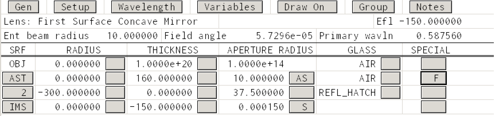
We can construct the system in OSLO with just three surfaces: OBJ, AST, IMS. The object, the aperture stop (which of course is the mirror) and the image surface. Everything is in air so it is super simple.
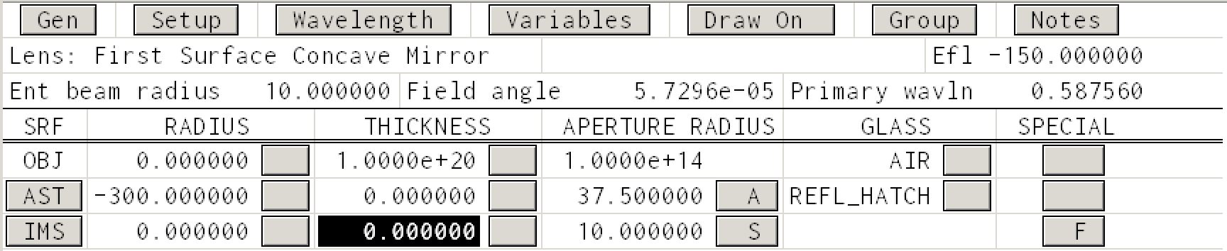
First, notice that in the glass column, we have selected REFL_HATCH to cause the rays to be reflected at this surface. (Either REFL or REFL_HATCH will reflect the light, it is just that the latter option indicates the opaque side of the mirror with hatching.)
Second, we get the expected effective focal length of -150mm in the upper right hand corner.
All this produces the rather disappointing ray trace
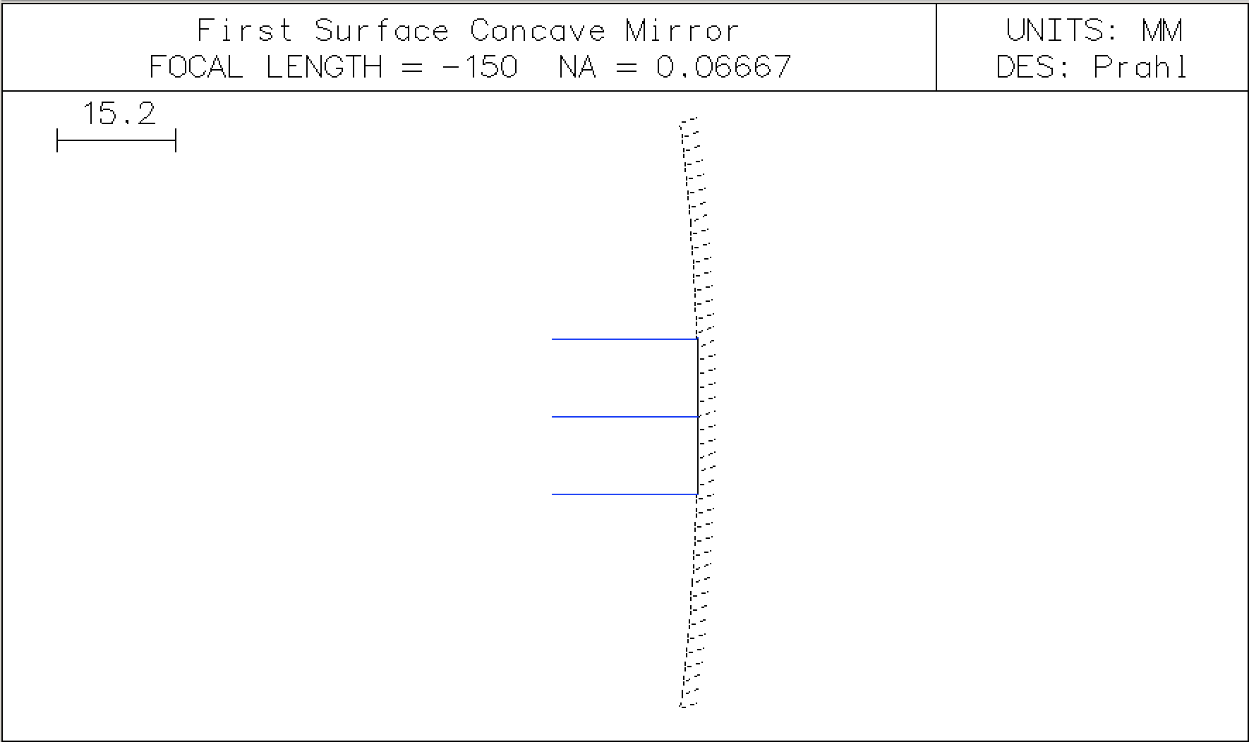
Showing the focus
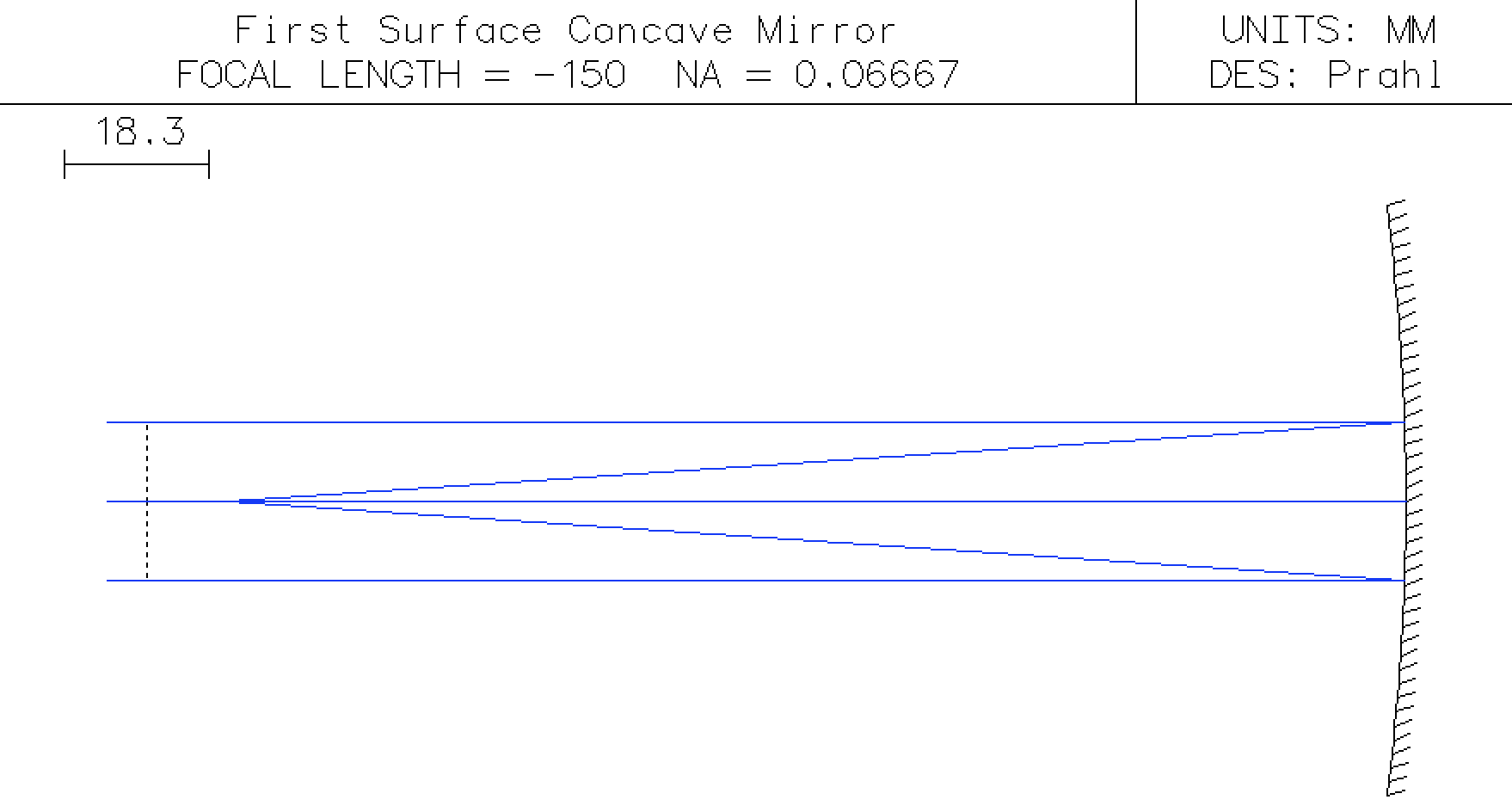
To improve this drawing, force OSLO to autofocus by clicking the THICKNESS -> Autofocus - paraxial focus button in the IMS column. Now we see
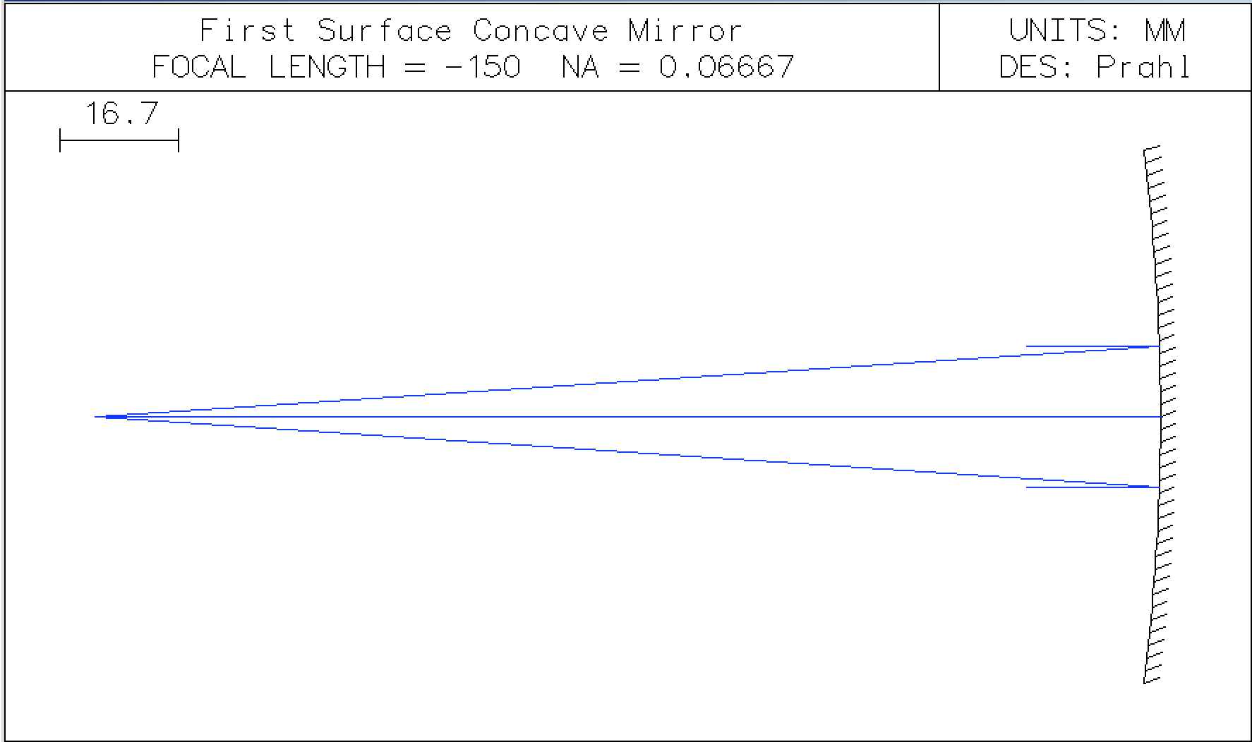
Showing the entering beam
Since I would like the rays to start farther to the left (at say 160mm from the mirror), one way is to create a new surface that has a specific aperture but does nothing else.
Insert a new row. In the APERTURE RADIUS column of the new row select APERTURE STOP (A). Next, in the SPECIAL column of this new row, select SURFACE CONTROL -> GENERAL to open a dialog box. Then in the Surface appearance in lens drawings select Drawn like shown below.
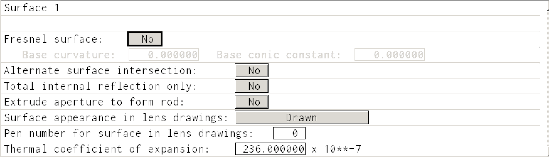
Then the Surface Data Table should look like
and the Autodraw window will look like
This OSLO lens file can be downloaded as concave-mirror.len
Concave mirror covered with glass
Let's assume that we have the same mirror, but now it is covered with 2mm of BK7 glass. What changes?
Well, now we have two more surfaces. The first is the air-glass surface for light entering the glass mirror and the second is for the glass-air surface for light leaving the mirror. So, we need to add rows to the lens data spreadsheet before and after the mirror surface.
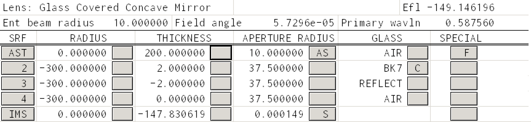
The first air-glass surface is straightforward. The radius of curvature is -300mm, the thickness of the glass is 2mm, the aperture is the same as the mirror, and the glass is BK7.
The reflecting surface now must be changed so that its
THICKNESSwill place the next surface at the correct location. After the reflection, light travels to the left and distances are now negative. Therefore the thickness to the next surface is -2mm. (Since the reflected rays are assumed to propagate in the same medium as before, the rays will still be in the BK7 glass.)The glass-air surface has the same radius of curvature and the same aperture radius as previous two surfaces. Leave the thickness as 0.
Finally, force OSLO to autofocus by clicking the
THICKNESS -> Autofocus - paraxial focusbutton in the IMS column again.
At this point the Surface Data Table should look like
And the ray trace looks like
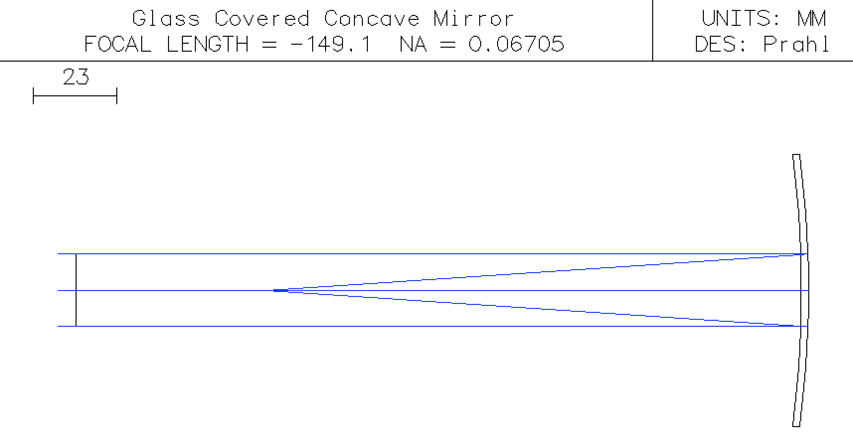
We see that the glass has modified the effective focal length from -150mm to -149.1mm.
Finally we can calculate the expected EFL using the paraxial approximation
n = 1.5168   #BK7 refractive index for the He line 587.6nm
R1= -300
R2= R1
d = 2
f =efl_thick_mirror(n,R1,R2,d)
print("The paraxial focal length of the mirror is %.1f mm" % f)
Next steps
The next tutorial will explore deeper mirror issues.
The final OSLO lens file for this mirror can also downloaded.
This document is also available as a Jupyter notebook as mirror.ipynb.
© 2019 Scott Prahl